Bringing AI Education to Life with Sn.AI.l
This summer I had the opportunity to intern at the Institute for Intelligent Systems and Robotics (ISIR) in Paris, France. During my internship I designed the full electrical architecture and core software systems for an AI educational robot. A big part of that work was turning the robot from a collection of modules into a single reliable hardware system that could power, control, and protect itself like a real product.
In this post, I’ll walk you through what the goal of this project was, what I did and why I did it, and finally, I’ll showcase a demo of Sn.AI.l.
Background
I was able to join the ISIR thanks to my tutorial supervisor, Louis Simon. After nagging him for many classes he recommended me to Dr. Nizar Ouarti, the director of the ASIMOV team at the ISIR which focuses on the interaction of robots with their environment. The day that my supervisor told me he talked to Dr. Ouarti I received a call from him. This call kept on getting better. As a first year university student I expected only to observe their work at the laboratory for a week or two. During this call not only did Dr. Ouarti grant me an internship where I would work directly on the project instead of observing but actually get paid for it. He was actually looking for someone to handle creating the interface for the project and communication between a computer and the robot. But this changed later.
A week or two after getting accepted I met one of my future coworkers, Louise, completely by chance. I was eating at the student cafeteria and I overheard someone speaking in English about Canada, my home country. I had to join in so we started talking about what she was doing in Paris. She told me that she is studying in Canada but currently interning at the ISIR for the summer, I said I’m also interning there for the summer. When I gave her my name she realized that we’d be working together, my future boss had told them I’d be joining them. What are the odds that we’d eat lunch at the same cafeteria, on the same day, at the same time, at the same table, right next to each other.
Louise introduced me to the project which got me even more excited.
The Goal
Artificial intelligence is driving today’s technological revolution, transforming the way we live and work. We encounter AI systems every day. As some jobs disappear and new ones emerge, it’s vital to equip future generations with the skills to understand and work alongside AI.
And this isn’t just for engineers — every field is touched by AI. In logistics, it can optimize delivery routes; in farming, it can automate crop care and milking. The next generation should have at least a foundational understanding of AI, both to use it effectively and to shape its impact.
That’s why we built Sn.AI.l, to make AI understandable, interactive, and fun.
Step 1 – Data
AI starts with data. With Sn.AI.l, students create and collect their own datasets by driving the robot and recording its sensor inputs. Then, with one click, they can train the robot and see the results immediately like racing Sn.AI.l through an obstacle course.
For those ready to go further, Sn.AI.l supports reinforcement learning, where the robot generates its own training data instead of relying on students to provide it. It learns entirely through trial and error, in the real world or in simulation, without any human-labeled datasets.
Step 2 – Algorithms
We don’t stop at data collection. Sn.AI.l’s interface makes AI algorithms, and the robotics concepts behind them, visible and intuitive. Students can start with simple methods like k-nearest neighbors and progress to deep neural networks, watching in real time as the robot’s “thinking” evolves.
Step 3 – Programming
With Sn.AI.l’s visual building-block interface, students can start coding with zero prior experience. They can create scripts for the robot to follow, respond to sensor data, and trigger AI models. With access to LiDAR, a depth camera, and motors, they can tackle classic robotics challenges like navigating in a room by detecting and avoiding obstacles and mapping its environment.
For advanced learners, full Python access opens the door to industry-standard tools and deeper control over every sensor, motor, and AI process.
In a world where AI shapes every industry, the ability to understand, experiment with, and innovate using intelligent systems will define the next generation’s opportunities.
My Role in Making Sn.AI.l
As mentioned before, I joined the project 2 weeks after my two coworkers, Louise and Mehdy. Lucky for me, they handled the less enjoyable phase of market research and planning.
I started out on the robot’s interface. The idea was simple: the robot would broadcast its own Wi-Fi network, and once connected, the user could go to snail.local to access a web interface.
To build this, I used HTML, CSS, and FastAPI. FastAPI handled two main jobs:
- Sending actions from the website to Python so the robot could respond.
- Streaming sensor data back into the web interface.
My first version had a homepage with a live camera feed and a D-pad for movement. It only took me two days to get it working, so after that quick win, I moved on to bigger challenges.
Electrical Design
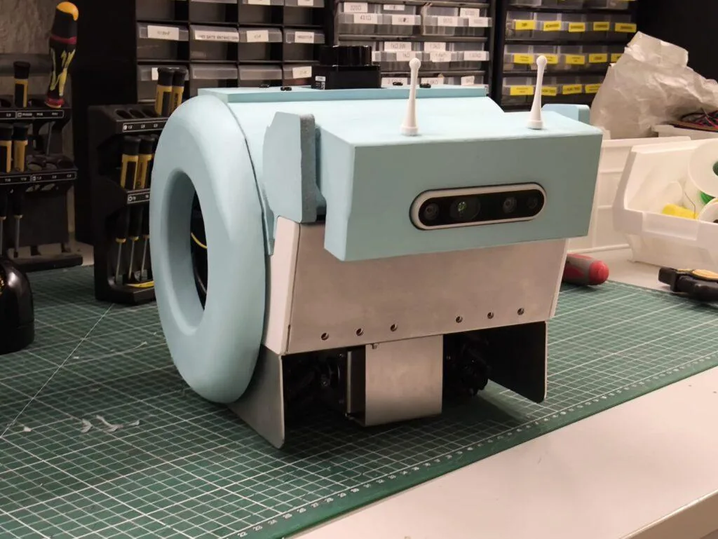
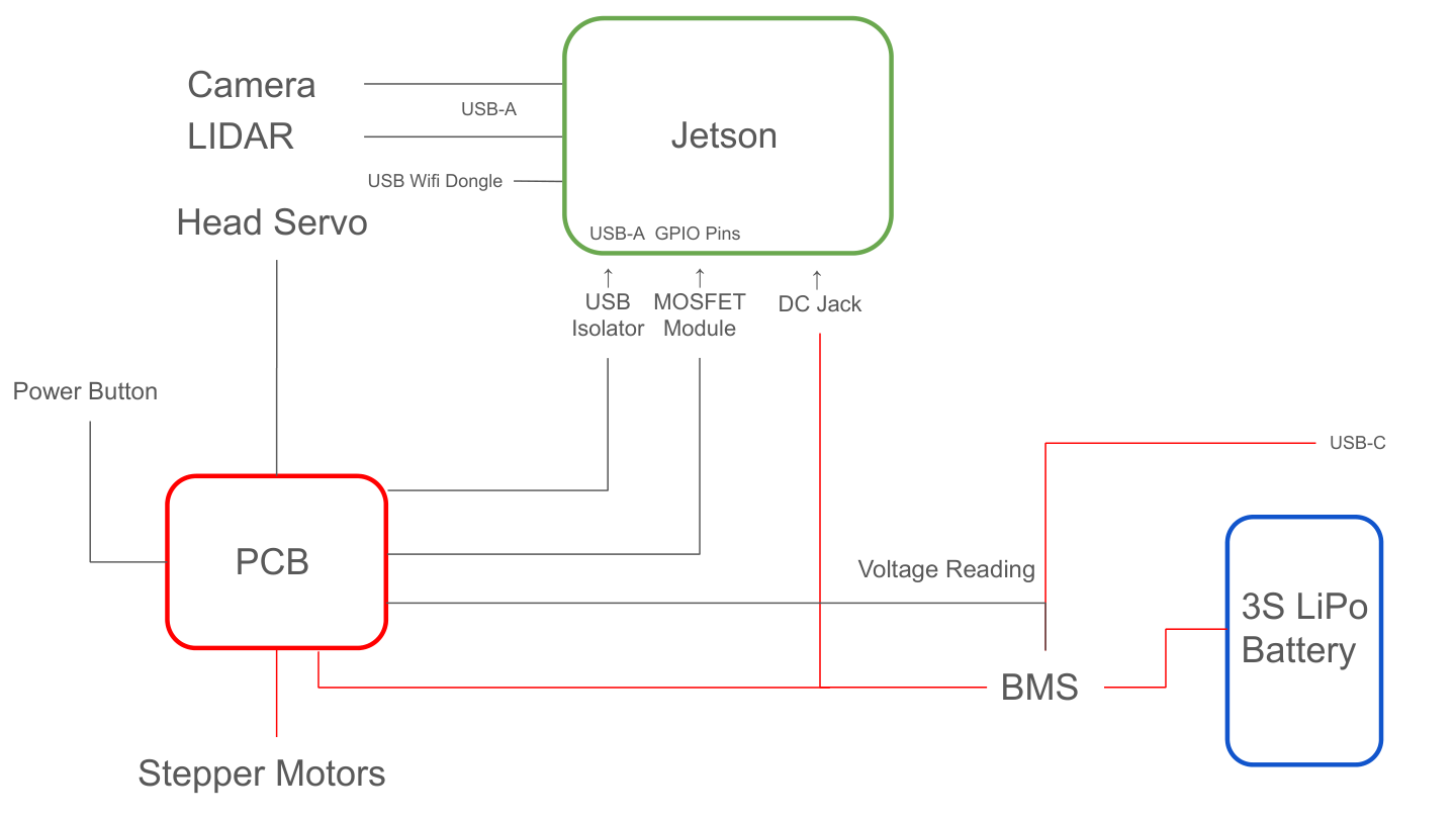
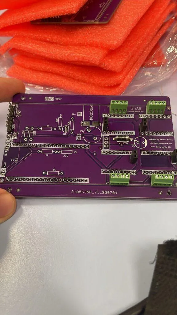
Once the interface was working, I moved to the part that made the robot viable as a product: the electronics. The goal was not just to drive motors, but to turn a pile of modules into a single power-and-control system. On the original prototype we had to think about the Jetson Orin Nano, four stepper motors, the head servo, battery monitoring, charging, odometry, and safe shutdown all at the same time. That was the point where a custom PCB became necessary.
Instead of treating the robot as a set of disconnected boards, I designed the electronics around one central controller: an ESP32. It gave me enough GPIO for the motion system, native Wi-Fi for the robot interface, and a clean way to talk to the Jetson over serial. I also moved the design to a 4-layer PCB, which helped keep the power routing cleaner and made the board much easier to trust once the motors started switching under load.
- Drive four TMC2209 stepper motor drivers for the wheels
- Control the head servo and leave room for future arm servos
- Measure battery voltage so the software could estimate battery percentage
- Integrate the LiPo battery, BMS, and USB-C charging path
- Handle safe power-up and soft shutdown for the Jetson Orin Nano
- Bring encoder signals into the system for odometry and navigation
Before the final board, I spent a lot of time prototyping on breadboards. That phase was messy, but it mattered: it let me validate the driver wiring, current limits, UART behavior, and shutdown sequence before I locked the design into copper. It also made the eventual PCB much more intentional, because every connector and pin assignment had already survived a real test setup.
Soft Shutdown System
Because the Jetson is a full computer, I could not treat power like a simple on/off switch. A hard cut risks filesystem corruption, so the board needed a real shutdown sequence. I tried a few MOSFET-only approaches first, but the gate-drive behavior and body-diode effects made them unreliable. What I eventually built was a button-triggered latch: the button wakes the board, the ESP32 holds the latch on, and a second press requests shutdown over USB before power is released.
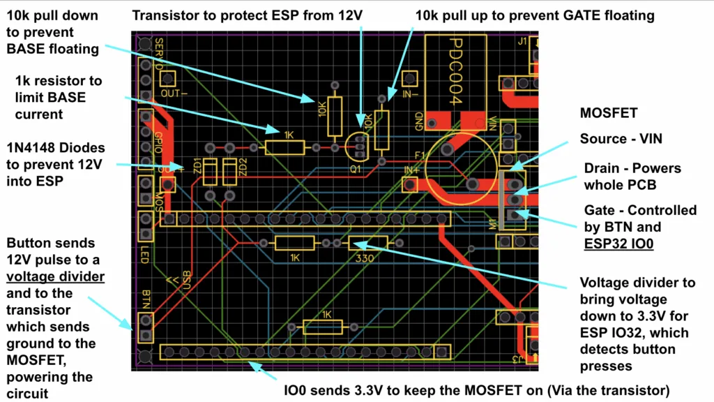
That circuit is a good example of the kind of hardware thinking the project demanded. The button is not just a switch — it is an input to a small power state machine. The ESP32 monitors the button through a voltage divider, waits for the Jetson to finish shutting down, and only then opens the latch. It made the robot behave like a real appliance instead of a bench prototype.
Power, Charging, and Protection
The board’s power path starts with 12V input, a fuse, and a P-channel MOSFET power switch. From there, the system feeds the stepper drivers and the rest of the robot electronics through regulated rails. I added a TVS diode and smoothing capacitor near the motor power path because stepper drivers are noisy loads and can kick energy back onto the supply rail when they decelerate or switch phases. Those parts help protect both the latch circuit and the Jetson from spikes.
I also built in LiPo battery support, a BMS, and USB-C charging so the robot could be operated and charged as a single system. That made the whole platform much easier to demo and much closer to something that could be used repeatedly in a lab setting. I also routed battery sensing into the ESP32 so the interface could show a meaningful battery percentage instead of just a raw voltage reading.
Motor Control and GPIO Budgeting
Control-wise, the ESP32 had to manage four stepper drivers, the head servo, the Jetson power enable, battery sensing, and the shutdown button input. Each TMC2209 driver needed STEP, DIR, and diagnostic/encoder lines, plus UART control for configuration. GPIO ran out quickly, which forced me to be disciplined about pin selection and boot-pin usage.
That constraint was actually helpful. It pushed me to think like a board designer instead of wiring signals one by one. I had to prioritize which signals belonged on the ESP32 directly, which ones could be shared, and which ones should be reserved for future expansion. In practice, that meant designing the board to handle the current robot cleanly while still leaving room for growth.
UART Communication
All four TMC2209 drivers share a single UART bus with the ESP32. The ESP32’s TX line fans out to the drivers, while the driver TX lines return through a resistor before reaching the ESP32 RX pin. That gave me software control over current limits, torque settings, and stall detection without dedicating a separate serial port to each motor driver.
What the Finished Board Changed
Once the PCB arrived, the whole robot felt much more coherent. The wiring was cleaner, the power path was safer, and the robot became something we could actually demo reliably. It also made the rest of the software work better: battery information was visible, the shutdown sequence was safe, and the motion stack was stable enough to support the AI and interface work above it.
Object Recognition
The next challenge was giving the robot the ability to see and understand its surroundings. My goal was to design a system that could detect everyday items out of the box, but also learn new, custom objects defined by the user.
The frontend is built with HTML/JavaScript, while the backend runs on a FastAPI server powered by multiple AI models. For general-purpose detection I used YOLOv5 (via ONNX Runtime for speed), and for custom object recognition I implemented NanoOWL alongside MobileNetV2 embeddings, using an Intel OAK-D depth camera.
Object Recognition Demo
Watch the object recognition demo on YouTube
Code Snippets
YOLOv5 for predefined objects (80+ COCO classes):
YOLOV5N_ONNX_PATH = 'yolov5n.onnx'
COCO_NAMES_PATH = 'coco.names'

with open(COCO_NAMES_PATH, 'r') as f:
    COCO_CLASSES = [line.strip() for line in f.readlines() if line.strip()]

ort_session = ort.InferenceSession(YOLOV5N_ONNX_PATH)
MobileNetV2 embeddings for user-defined objects:
mobilenet = mobilenet_v2(pretrained=True)
mobilenet_embed = torch.nn.Sequential(
    mobilenet.features,
    torch.nn.AdaptiveAvgPool2d((1, 1)),
    torch.nn.Flatten()
)
Key Technical Challenges
- Running multiple AI models efficiently — Moved YOLOv5 to ONNX Runtime for faster inference, added a configurable sliding-window stride, and scheduled YOLO runs first with custom detection filling in the gaps.
- Bounding box misalignment between models — Wrote a scaling/transform function to map YOLO’s resized inputs back to the original frame cleanly.
- Adding real-world distance measurements — Combined YOLO detections with OAK-D depth frames. For each bounding box, the system computes the average depth inside the region.
Blockly Editor
Once the robot had vision and recognition capabilities, the next step was to give users a way to program behaviors without writing code. To achieve this, I built a robot control interface that combines visual programming with real-time computer vision and robotics.
The environment includes both a Blockly-based visual editor and a Python text editor, all connected to a FastAPI backend that communicates with the physical robot.
Blockly Editor Demo
Watch the Blockly editor demo on YouTube
The blocks are organized into intuitive categories:
- Events: script triggers (e.g. “when flag clicked”)
- Motion: robot movement commands
- Line Following: specialized blocks for tracking lines
- Control: loops, conditionals, and flow control
- Sensing: object detection and distance measurement
- Operators: logic and math operations
Live Camera Feed
The interface integrates the live vision system so programs can react to the environment:
function checkCameraUsage() {
    const code = Blockly.JavaScript.workspaceToCode(blocklyWorkspace);
    const usesCamera = code.includes('isObjectDetected') ||
        code.includes('getObjectDistance');

    if (usesCamera) {
        cameraContainer.style.display = 'flex';
        startCameraFeed();
        startDetectionTracking(code);
    }
}
Robot movement commands are passed over serial to an Arduino controller:
def move_robot_command(action: str):
    if ser and ser.is_open:
        command_to_send_to_arduino = f"{action}
"
        ser.write(command_to_send_to_arduino.encode('utf-8'))
        return {"status": "ok", "received": action}
Jetson Orin Nano Setup
Since we needed SLAM and Reinforcement Learning on the Jetson, I opted to install an NVMe SSD. The first one that I bought was a PNY CS1030. I tried multiple methods to get it working but nothing worked.
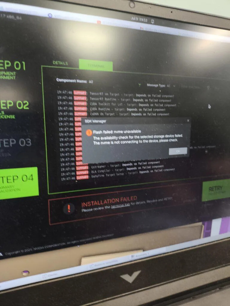
Finally, I bought a Lexar NM620 instead which worked perfectly right away. The problem was that the CS1030 lacked a DRAM cache, meaning it couldn’t keep its mapping table in fast memory and had no Host Memory Buffer support to fall back on.
SLAM
I chose RTAB-MAP SLAM for this project because it could generate voxelized 3D maps of the environment and supported LiDAR and wheel odometry inputs. I could have used NVIDIA’s Isaac SLAM which is more optimized for the Jetson Orin Nano, but it didn’t support LiDAR input or wheel odometry.
RTAB-MAP was installed via Docker (building from source on ARM was painful). I used three.js to visualize the point cloud on an HTML page.
The system works seamlessly: an HTTP request triggers the start, the FastAPI backend spawns rtabmap, and the status is checked every 5 seconds — students don’t need to touch the command line.
Assembly
When my new PCB arrived, everything worked perfectly — except the soft shutdown system. It would behave very strangely: sometimes it wouldn’t turn on, other times it wouldn’t turn off.
What I thought would be a quick fix turned into three long days of debugging. In the end, the solution was surprisingly simple: replacing the BJT transistor with an N-channel MOSFET.
Conclusion
Building Sn.AI.l was an incredible experience that taught me more than any classroom ever could — from PCB design and soft shutdown circuits to computer vision pipelines and visual programming interfaces. The robot is now capable of teaching students the full AI pipeline: collect data, train models, and deploy on a real robot.