I redesigned the electrical system for Sn.AI.l to turn a collection of modules into a single integrated robot. The PCB became the central power and control hub, connecting the Jetson Orin Nano, motor control, the neck servo, charging and battery management, soft shutdown, and wheel-encoder odometry.
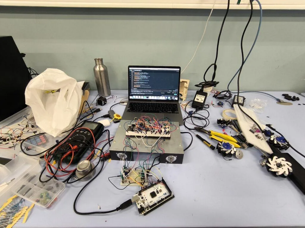
At first I prototyped the system with breadboards and temporary wiring, but it quickly became clear that the robot needed a dedicated board. Moving to a custom PCB was the point where the electrical side started to feel like a real system rather than a patchwork of parts.
What the board needed to handle
The PCB was responsible for more than power distribution. It had to act as the electrical interface between the compute stack, motion system, battery system, and user controls:
- Connect the Jetson Orin Nano to the motor control electronics
- Drive the neck servo
- Handle charging through the battery management system
- Measure battery voltage for battery percentage
- Support a proper soft shutdown sequence
- Read wheel-encoder odometry
That combination pushed me toward a custom 4-layer PCB with an ESP32 at the center of the control logic.
From prototype to system architecture
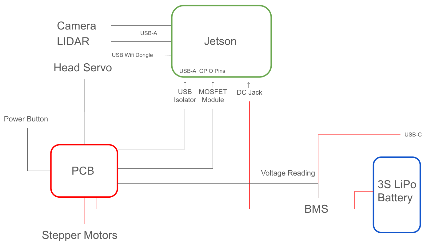
One of my goals was to make the architecture understandable and maintainable. I built the design around a clear power path so the Jetson, motors, camera, LiPo battery, BMS, USB charging, and PCB all worked together as one system instead of separate modules.
That design pass made a big difference: it forced me to think about the robot as an integrated product, not just a collection of subsystems.
PCB layout and integration
The board layout is where the tradeoffs became real. I had to fit the stepper driver circuitry, ESP32, servo control, Jetson power control, protection components, connectors, and the power path into a compact board that could actually fit inside the robot shell.
Getting there took iteration. I revised connectors, rerouted messy sections, and simplified the layout until it felt robust enough to trust in a real robot.
Power, charging, and battery monitoring
Battery behavior mattered a lot to me because I wanted the robot to feel dependable in practice. The system uses a LiPo battery with a BMS so it can be charged safely and monitored properly.
I also added voltage measurement so the software could estimate battery percentage instead of guessing. That made the robot much easier to operate during demos and test sessions.
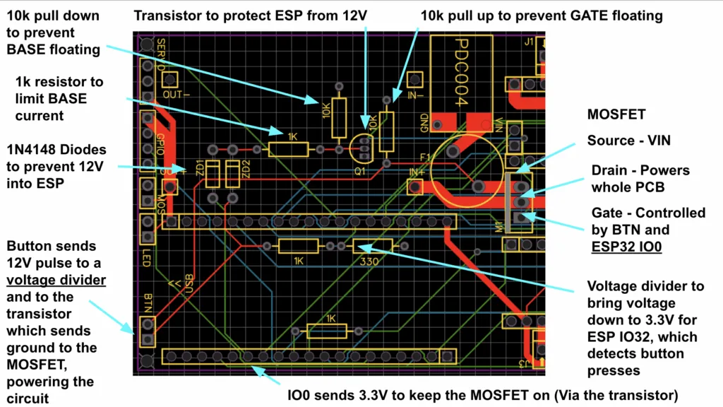
Soft shutdown and safe power control
Because the Jetson is a full computer, I could not treat power like a simple toggle. A hard power cut could corrupt files or leave the system in a bad state, so I built a soft shutdown circuit.
The idea was to let the robot wake cleanly, stay latched while it was running, and then shut down in an orderly way when requested. It took a lot of testing to make that behavior reliable.
Why odometry mattered
I brought the wheel-encoder signals onto the board so the software could estimate odometry. That gave the robot a better sense of distance and heading, which is important for navigation and overall system behavior.
It is one of those details that is easy to overlook, but it makes the whole robot feel much more complete.
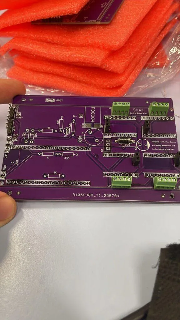
The finished PCB
Seeing the finished PCB installed in the robot was the best proof that the electrical work had paid off. It was no longer just a schematic or a layout file — it was a functioning control board tying the whole system together.
What I took away from it
This project taught me a lot about building real hardware systems: power distribution, charging, safe shutdown, sensor integration, layout tradeoffs, and making all the pieces work together reliably.
Designing the PCB made Sn.AI.l feel much closer to a real robot product and much less like a prototype.