September 2026 · Built prototype · Bench and shallow-water trials
I am developing a modular remotely operated underwater vehicle (ROV) that brings together mechanical design, embedded firmware, live video, and variable ballast. The ROV has progressed from CAD to an assembled prototype with twin thrusters and a browser-based control console connected through an Ethernet tether.
My work spans the complete integration: designing and iterating the printed assemblies, packaging the electronics and plumbing, integrating control and sensing, and using physical tests to guide the next revision. The vehicle is remotely piloted, with sealing, ballast performance, and endurance evaluated through bench and shallow-water tests.
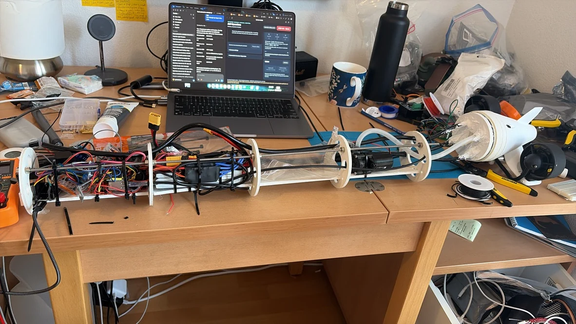
- Mechanical: a 700 mm hull with an extractable electronics sled, transparent camera dome, and serviceable twin-thruster tail.
- Embedded and software: a two-ESP32 architecture, Ethernet video and telemetry, differential steering, reversible ballast, and fault-aware controls.
- Test evidence: working camera transport and control integration on the bench, plus assembled-vehicle propulsion trials in shallow water.
Designing for access, not just fit
The hull is a 700 mm long PVC tube, 100 mm outside diameter and 94 mm inside diameter. A transparent forward dome gives the camera a view out of the vehicle. Inside, a removable sled carries the electronics, battery, ballast bag, and pump between printed supports and longitudinal rods.
The narrow diameter makes packaging a systems problem: hose bend radii, connectors, cable routing, and maintenance access compete for the same space. I revised the pump installation and rear geometry around those constraints rather than treating the exterior and internals as separate designs.
The current tail combines a straight conical fairing, one dorsal fin, blended motor supports, a pressure-probe cradle, and cable passages. It screws onto a separate mounting interface at the rear plug, allowing the fairing to be replaced without rebuilding the sealed penetrations. The flooded nose and tail fairings shape the exterior; the PVC tube, plugs, dome, O-rings, and penetration seals form the pressure boundary.
Interactive CAD · Current revision
Explore the current build
Rotate the full vehicle or inspect the printed end assemblies.
Full vehicle
700 mm hull · twin thrusters · current nose and tail
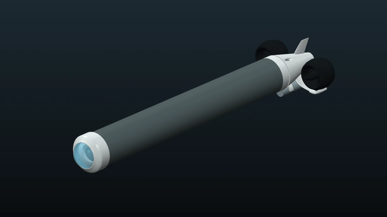
CAD preview shown. Interactive view loads as you scroll here.
Straight-cone tail
V8 print geometry · single fin · integrated motor supports
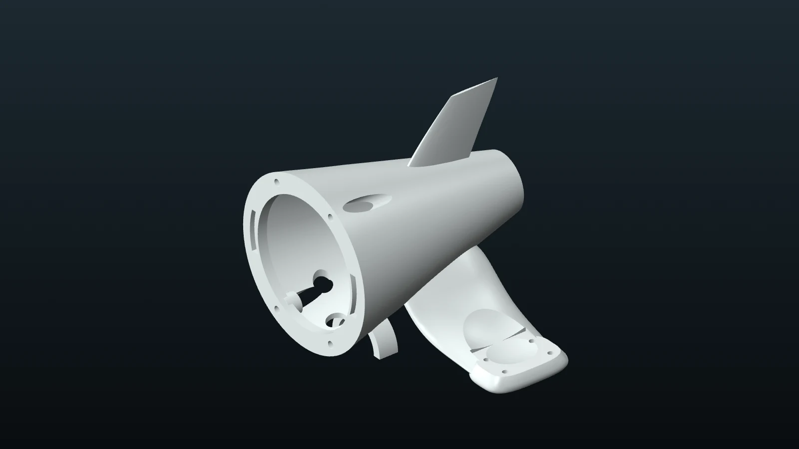
CAD preview shown. Interactive view loads as you scroll here.
Dome and nose assembly
Revised fairing · front plug · transparent dome proxy
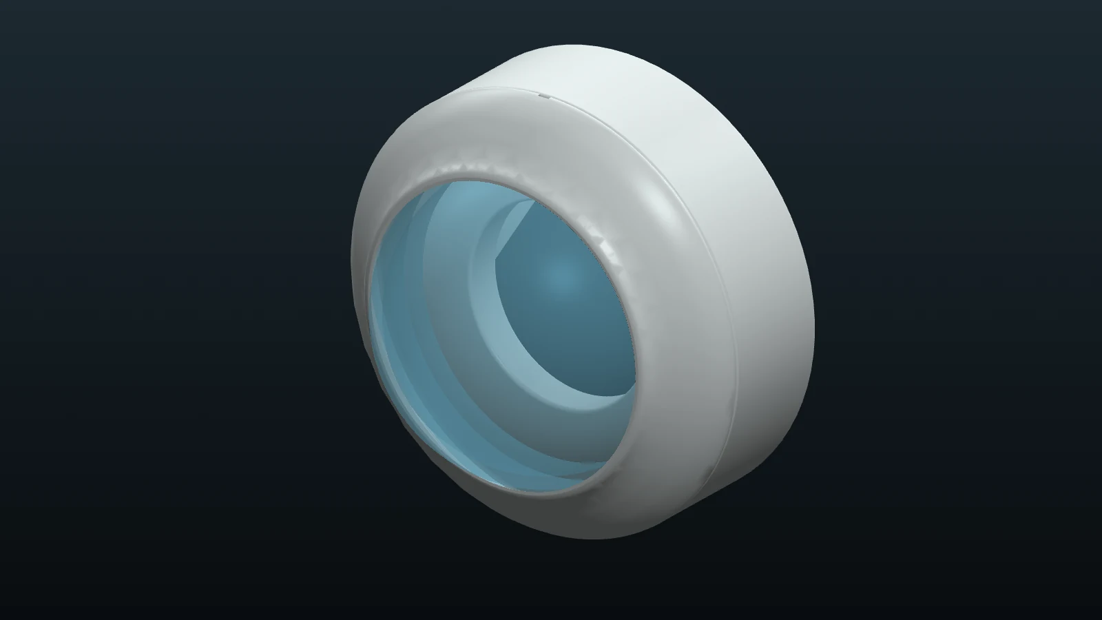
CAD preview shown. Interactive view loads as you scroll here.
Current V8 straight-cone tail and revised 80 mm dome fairing. Thrusters and the pressure probe are dimensional proxies; wiring, hoses, sealant, rubber sleeve, and clamps are omitted. Views are independently scaled and are presentation assemblies, not new print releases.
From CAD to structural analysis
The structural study examines how external pressure loads the hull, dome and printed closures, and how the twin-thruster supports carry an offset thrust load. It uses the current CAD geometry with Gmsh quadratic solid meshes, CalculiX elastic analysis and Python post-processing.
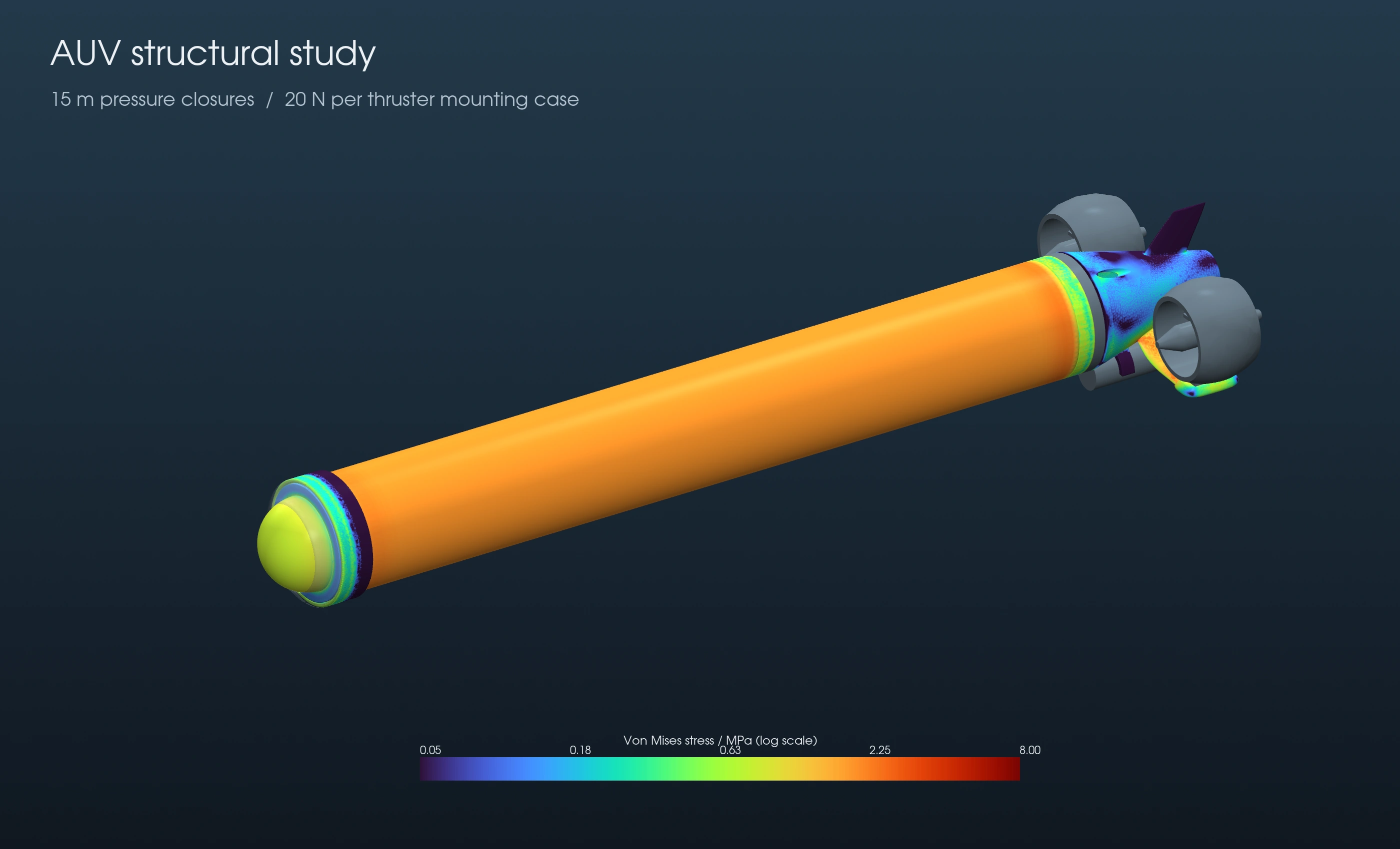
- Pressure case
- 147.1 kPa
- Closure load
- 1.155 kN
- Mounting case
- 20 N / motor
15 m freshwater differential
Equivalent axial end load
Axial load with bending
Follow the load path
The 700 mm PVC hull has a 100 mm outside diameter and a 3 mm wall. The pressure case combines exterior pressure with the equivalent closed-end load. At the hull midspan, the inner-wall von Mises stress is 2.19 MPa and inward radial movement is 0.028 mm.
At the front, pressure on the 3 mm acrylic dome transfers through its flange into the printed socket. At the rear, the plug transfers the equivalent end load through its seating shoulder. Idealized attachments isolate each component's response; O-rings, cable potting, adhesive and the rubber sleeve/clamps are not represented by a contact or leakage model.
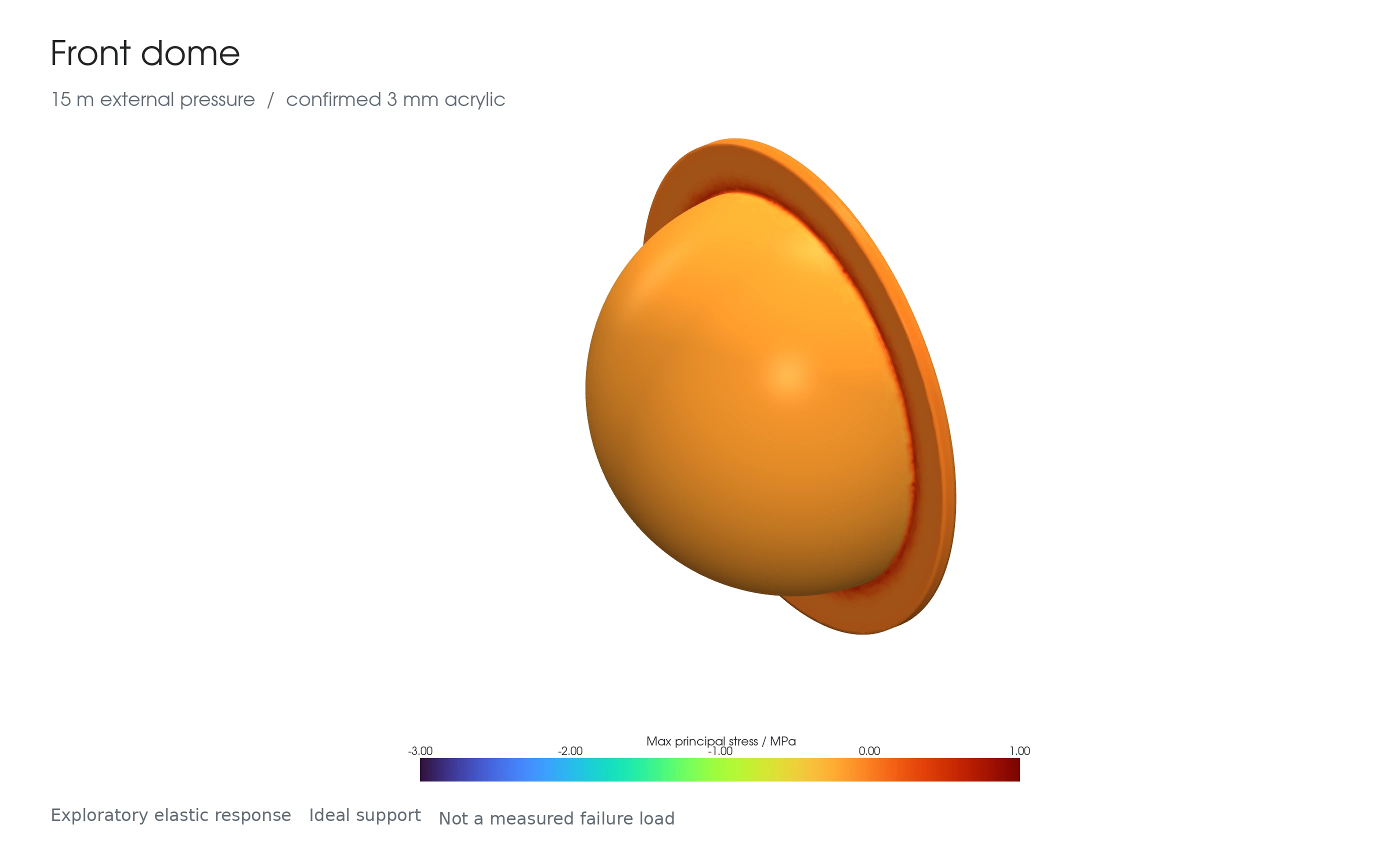
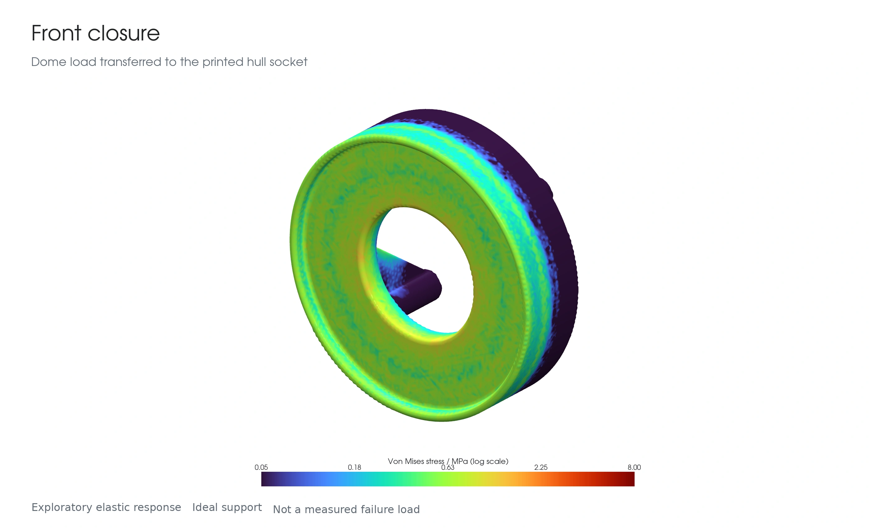
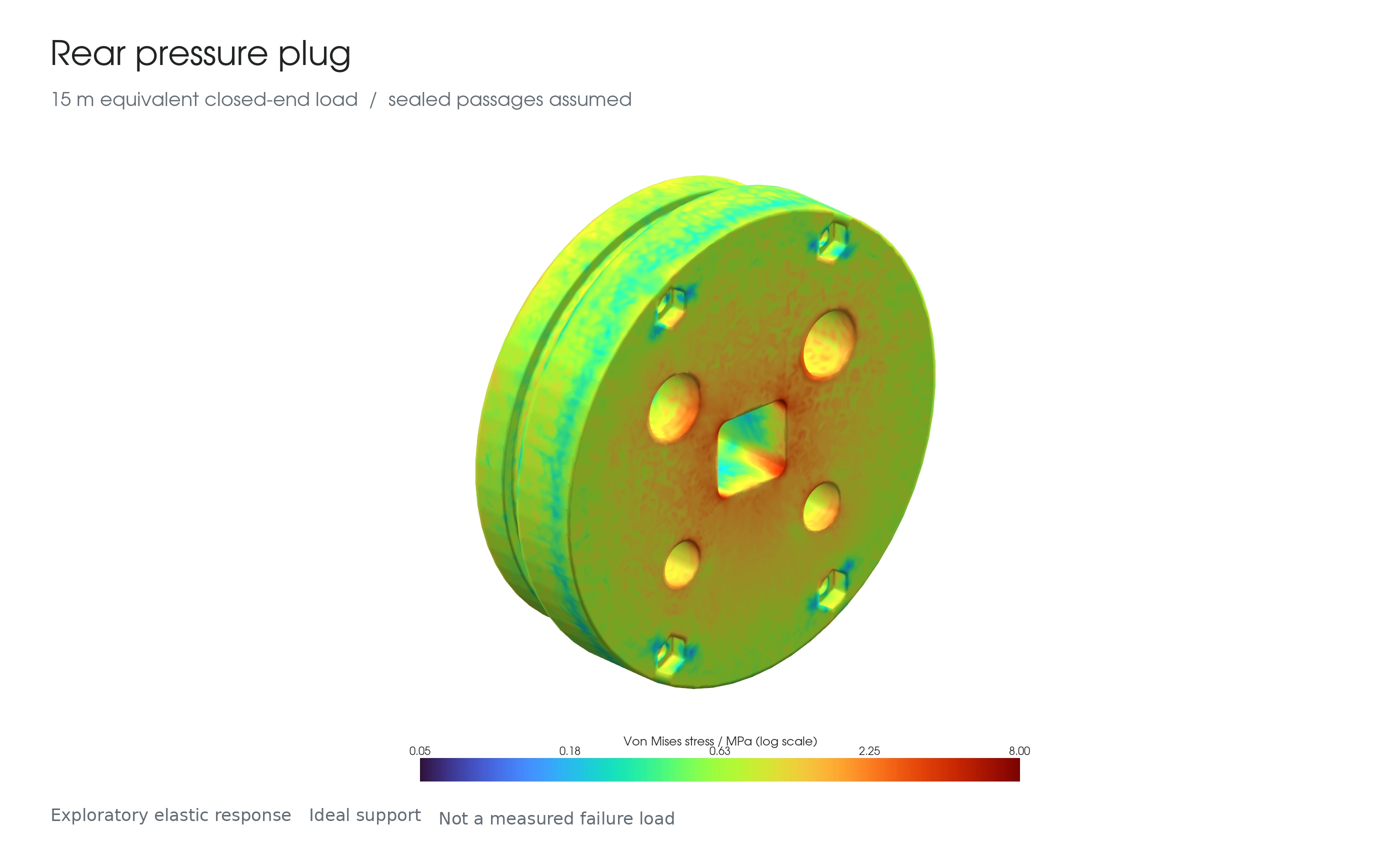
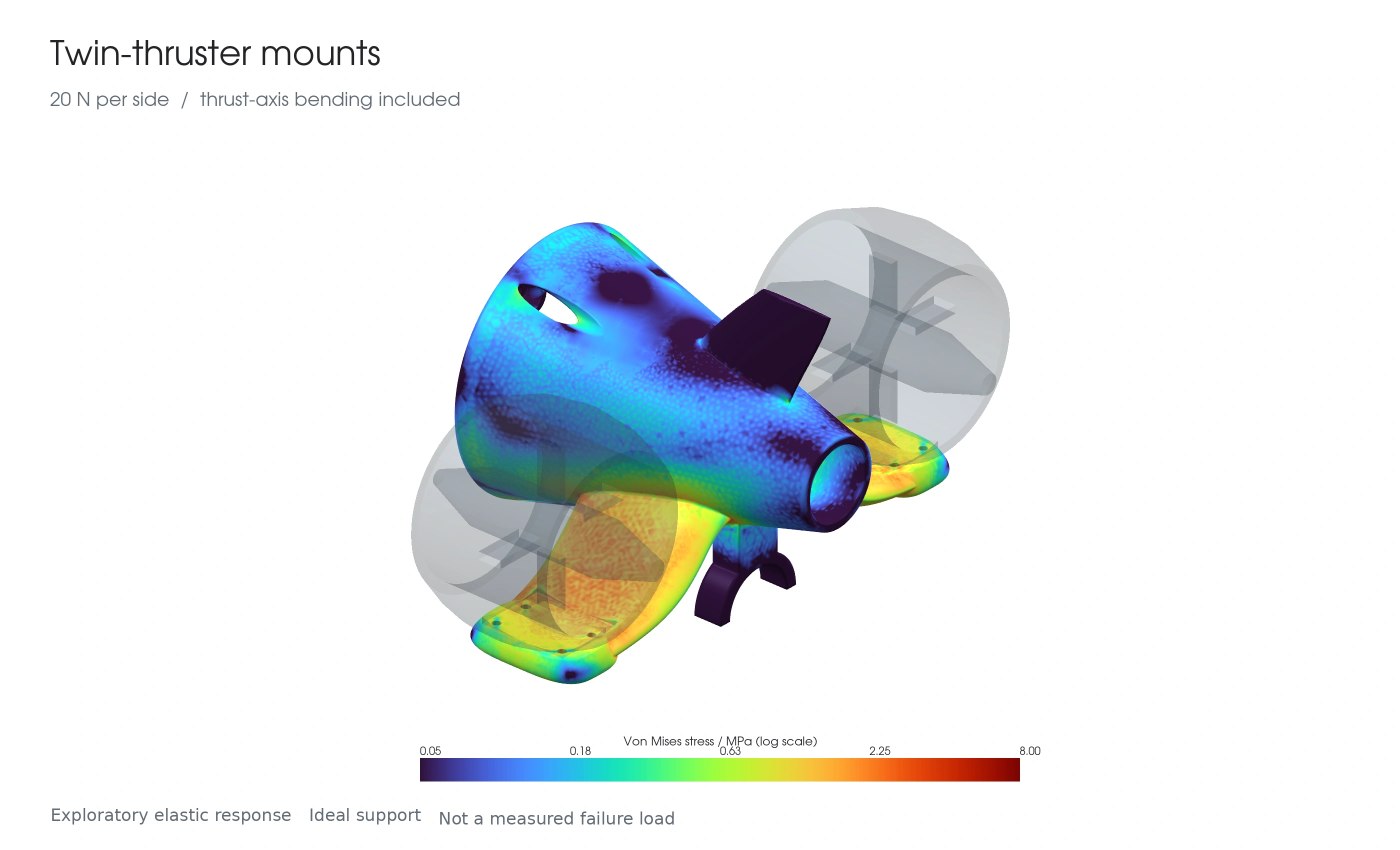
The tail is flooded, so it does not carry the sealed hull's pressure differential. Its separate load case includes the 41.68 mm offset between the thrust axis and mounting seat, represented by a force and bending couple. This is a mounting study, not a measured thruster limit; impact, torque and fastener contact remain separate questions.
Model verification
The hull's midspan stress agrees with the analytical cylinder solution within 0.054%. Force/reaction balance closes within 0.001%, and the sampled quadratic-element Jacobians are positive. Refinement changes maximum displacement by 0.03% for the dome, 11.8% for the front closure, 1.8% for the rear plug and 3.9% for the tail. The front closure remains mesh-sensitive; local stress peaks are not treated as converged fracture predictions.
Material and modeling assumptions
Representative short-term elastic properties are used: PVC E = 3.2 GPa and acrylic E = 2.8 GPa. The dome's material and 3 mm thickness are confirmed; its 80 mm diameter and flange shape follow the existing CAD.
Printed parts use an approximate 1.25 mm skin with E = 2 GPa around a weak core with E = 0.2 GPa. The core stiffness is an assumed continuum value, not a property inferred from the rear plug's 10% infill. Layer adhesion, anisotropy, toolpaths, creep and water aging are not explicitly resolved. Skin/core assignment and ideal restraints influence local stress patterns.
15 m is an analysis case, not a qualified operating depth. These elastic results do not establish a breaking depth. External-pressure buckling, printed-layer failure, joint retention and sealing still require dedicated analysis and physical validation. A preliminary generic hull buckling screen is sensitive to ovality and load duration, so low elastic displacement alone does not demonstrate safety.
Components and design decisions
I prioritized affordable, available modules that could fit the hull and support incremental testing. The choices below describe the current prototype—not the earlier proposed component list.
| Component | Why it fits this design |
|---|---|
| ESP32-WROOM DevKit + ESP32-CAM | A compact, low-cost split between camera acquisition and the main controller. The ordinary ESP32 provides accessible GPIO for control and sensing; a dedicated SPI link carries camera frames to it. This avoids adding a Linux single-board computer, at the cost of limited video throughput. |
| W5500 Ethernet interface | One wired tether carries video, telemetry, and commands without relying on an underwater Wi-Fi connection. The trade-off is cable drag and a communications path that needs explicit disconnect recovery. |
| 2 × APISQUEEN U2 Mini thrusters + independent ESCs | Compact ducted propulsion with differential steering: varying left and right thrust avoids adding a moving rudder linkage. Their size and mounting loads drove several tail and motor-support revisions. |
| ZC-A210 reversible gear pump + bidirectional motor driver | The smaller pump fits the constrained internal bay and allows one pump to fill and empty the ballast bag. Installed flow and pressure capability still need characterization with the hull closed. |
| Nominal 500 mL flexible ballast bag | A low-cost reservoir that conforms to the available space. Adding water changes vehicle mass without changing external volume, but the expanding bag compresses the sealed hull air and needs kink-free plumbing. |
| 4–20 mA pressure probe + current-to-voltage converter | A packaged submersible probe keeps the pressure-sensing element outside the hull. The converter makes its current output readable by the ADC; the assembly is bulky and requires calibration against known depths. |
| ADS1115 ADC + battery divider + leak probe | One external ADC collects the conditioned pressure signal, divided battery voltage, and a simple two-electrode water-detection input. Shared diagnostics and saved calibration make faults more visible; the leak probe is a backup, not a seal or power isolator. |
| MPU6050 inertial sensor | A compact, inexpensive source of acceleration and angular-rate data for attitude monitoring in the piloting console. |
| 3S battery + regulated 5 V UBEC | Battery power serves the actuators while the UBEC supplies the low-voltage electronics. This separates voltage requirements, not electrical grounds; power integrity remains part of integrated testing. |
| PVC hull + PLA printed assemblies | A readily available cylindrical enclosure and fast, inexpensive geometry iteration on a FlashForge Dreamer. Removable interfaces reduce rework, while sealing surfaces and printed parts still require physical validation. |
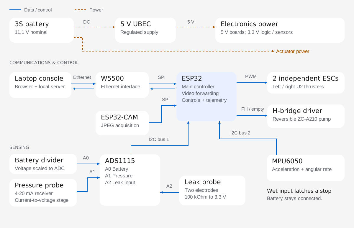
From camera frames to a piloting console
The main ESP32 handles Ethernet, control, and sensor acquisition; the ESP32-CAM sends captured frames over a dedicated internal SPI link. A local laptop service presents the live feed, battery and depth readings, sensor state, and commands in a browser.
Measured bench result: two receiver tests totaling 500 frames delivered 800 × 600 JPEG video at 7.42–7.56 fps, with a maximum arrival gap below 153 ms. This characterizes the camera transport under the recorded bench conditions, not end-to-end display latency or in-water endurance.
The operating console supports W/A/D steering, on-screen controls, and hold-to-fill/empty ballast commands. Releasing a control, leaving the active window, or losing fresh communication clears motion commands. Reconnection requires new input rather than resuming a previous movement.
Battery voltage is calibrated against a multimeter and retained in non-volatile storage. The pressure input has a saved atmospheric zero; its depth scale remains provisional until checked against known immersion depths.
Engineering the failure cases
I added a conductive leak probe and a visible water-detected warning. A wet reading latches a software stop for the thrusters and pump; it does not disconnect the battery. Network recovery also preserves the leak latch and clears stale motion commands.
Intermittent connection failures led to a more explicit recovery sequence: invalidate commands, stop outputs, rebuild the Ethernet services, and initialize the ESC signal channels at idle before accepting fresh input. A controlled console-outage test restored video and the idle controller state without rebooting either ESP32. Further battery-powered testing is needed to resolve the original intermittent fault and validate recovery with powered actuators.
The ballast system exposed a different integration problem. Early filling tests moved less water than expected; later tests improved. I am checking excess service-loop tubing for kinks and priming restrictions, alongside the backpressure caused by compressing air in the sealed hull. There is no fitted flow or bag-volume sensor, so run time is not reported as a measured fill percentage.
Built, tested, and still improving
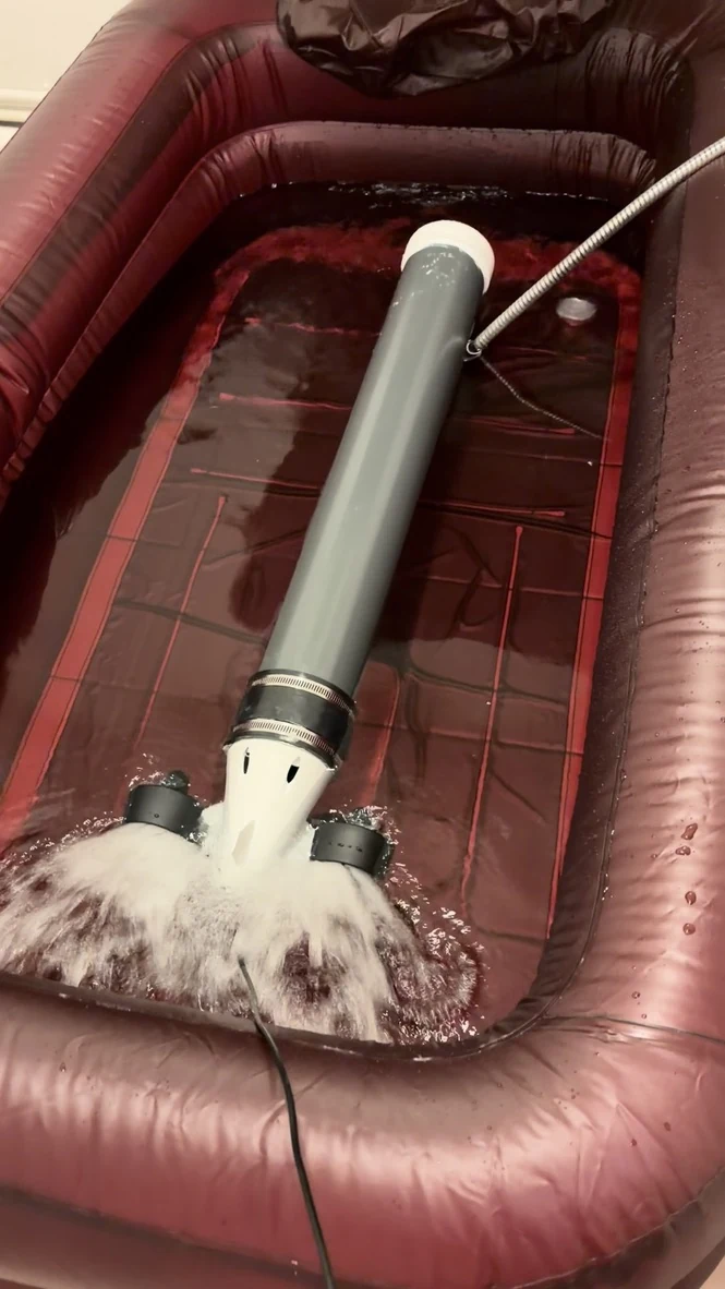
The pool trials put the packaging, propulsion, and seals into the same physical test. They demonstrate an assembled vehicle with operating twin thrusters—not just a CAD concept or isolated electronics.
Immersion checks also revealed small leaks, with cable penetrations appearing to be one source. Reworking and isolating those paths is now a validation task. The vehicle does not yet have a qualified operating depth.
Next milestones: repeatable dry-hull immersion tests, measured fill/empty performance with the hull closed, longer battery-powered runs, and controlled trim and depth-calibration checks.
The main outcome so far is a serviceable electromechanical prototype and a testable control stack. The project has sharpened how I work across subsystem boundaries: turning packaging constraints into CAD revisions, turning observed faults into firmware behavior, and distinguishing a demonstrated result from a design assumption.