This summer I’ve had the opportunity to intern at the Institute for Intelligent Systems and Robotics (ISIR) in Paris, France. During my internship I designed the full electrical architecture and core software systems for an AI educational robot.
In this post, I’ll walk you through what was the goal of this project, what I did and why I did it, and finally, I’ll showcase a demo of Sn.AI.l.
Background
I was able to join the ISIR thanks to my tutorial supervisior, Louis Simon. After nagging him for many classes he reccomended me to Dr. Nizar Ouarti, the director of the ASIMOV team at the ISIR which focuses on the interaction of robots with their environment. The day that my supervisor told me he talked to Dr. Ouarti I recieved a call from him. This call kept on getting better. As a first year university student I expected only to observe their work at the laboratory for a week or two. During this call not only did Dr. Ouarti grant me an internship where I would work directly on the project instead of observing but actually get paid for it. He was actually looking for someone to handle creating the interface for the project and communication between a computer and the robot. But this changed later.
A week or two after getting accepted I met one of my future coworkers, Louise, completly by chance. I was eating at the student cafeteria and I overheard someone speaking in English about Canada, my home country. I had to join in so we started talking about what she was doing in Paris. She told me that she is studying in Canada but currently interning at the ISIR for the summer, I said I’m also interning there for the summer. When I gave her my name she realized that we’d be working together, my future boss had told them I’d be joining them. What are the odds that we’d eat lunch at the same cafeteria, on the same day, at the same time, at the same table, right next to eachother.
Louise introduced me to the project which got me even more excited.
The Goal
Artificial intelligence is driving today’s technological revolution, transforming the way we live and work. We encounter AI systems every day. As some jobs disappear and new ones emerge, it’s vital to equip future generations with the skills to understand and work alongside AI.
And this isn’t just for engineers, every field is touched by AI. In logistics, it can optimize delivery routes; in farming, it can automate crop care and milking. The next generation should have at least a foundational understanding of AI, both to use it effectively and to shape its impact.
That’s why we built Sn.AI.l, to make AI understandable, interactive, and fun.
Step 1 – Data
AI starts with data. With Sn.AI.l, students create and collect their own datasets by driving the robot and recording its sensor inputs. Then, with one click, they can train the robot and see the results immediately like racing Sn.AI.l through an obstacle course.
For those ready to go further, Sn.AI.l supports reinforcement learning, where the robot generates its own training data instead of relying on students to provide it. It learns entirely through trial and error, in the real world or in simulation, without any human-labeled datasets. In a world where there’s only so much data people can create, this ability to learn independently is what powers many of today’s AI systems. That same technology is now in the hands of those who will shape that future.
Step 2 – Algorithms
We don’t stop at data collection. Sn.AI.l’s interface makes AI algorithms, and the robotics concepts behind them, visible and intuitive. Students can start with simple methods like k-nearest neighbors and progress to deep neural networks, watching in real time as the robot’s “thinking” evolves.
Step 3 – Programming
With Sn.AI.l’s visual building-block interface, students can start coding with zero prior experience. They can create scripts for the robot to follow, respond to sensor data, and trigger AI models. With access to LiDAR, a depth camera, and motors, they can tackle classic robotics challenges like navigating in a room by detecting and avoiding obstacles and mapping it’s envirnoment. They can experiment with reinforcement learning right from this interface, teaching the robot to accomplish tasks such as navigating an unfamiliar maze or following a moving object.
For advanced learners, full Python access opens the door to industry-standard tools and deeper control over every sensor, motors, and AI process.
In a world where AI shapes every industry, the ability to understand, experiment with, and innovate using intelligent systems will define the next generation’s opportunities. By enabling students to collect data, explore algorithms, and program real-world robots, Sn.AI.l equips them with the tools to thrive in an AI-driven world.
My Role in making Sn.AI.l
As mentioned before, I joined the project 2 weeks after my two coworkers, Louise and Mehdy. Lucky for me, they handled the less enjoyable phase of market research and planning.
I started out on the robot’s interface. The idea was simple: the robot would broadcast its own Wi-Fi network, and once connected, the user could go to snail.local to access a web interface.
To build this, I used HTML, CSS, and FastAPI. FastAPI handled two main jobs:
- Sending actions from the website to Python so the robot could respond.
- Streaming sensor data back into the web interface.
My first version had a homepage with a live camera feed and a D-pad for movement. It only took me two days to get it working, so after that quick win, I moved on to bigger challenges.
Electrical Design
Next up: the electrical design. I began with the most important aspect, motor control. The inital arcitechture planned out by my colleagues would use a SKR MINI E3 V3.0 Control Board to control 4 stepper motors. I decided to opt for a custom PCB instead.
I chose this solution because we needed to have a soft shutdown circuit as we would have a Jetson Orin Nano onboard, which is a small computer specialized for AI to handle all of the robot’s AI needs. You can’t just cut power to it as it can corrupt files. We also needed to read battery voltage to display battery percentage, control a servo motor for the head tilt of the snail and potentially control 5 more for a robot arm, and have 4 encoders for the 4 wheels.
This wouldn’t be possible on the SKR MINI E3 because it’s only built for motor control. We could either stack a custom PCB on top of it, or design one single board to handle everything. Cost, simplicity, and flexibility all pointed toward one big custom PCB.
So I began prototyping. I started on a breadboard with four stepper drivers and a hacked-up 12V power supply (I literally cut the DC jack off to wire it directly). Sketchy? Yes. But it worked.
Finding proper documentation for the drivers was a pain, and setting the VREF (a voltage that controls how much current the motor gets) was trial-and-error. Add to that a jungle of wires, and mistakes were easy, so easy that I fried more drivers than I’d like to admit. Louise even made memes about it.


Once I got the motors spinning, I added UART-based torque control and stall detection. At this point I needed two breadboards just to fit all the wiring. Needless to say, I was eager to move to a PCB. But the messy prototype phase was necessary to confirm the wiring.
The final challenge before the PCB design was the soft shutdown system. The goal: let the user power on the robot with a button, and ensure the Jetson shuts down safely before cutting power.
Soft Shutdown System
Initially I just wanted to use one MOSFET, which is basically an ON/OFF switch but instead of being flipped physically it’s controlled by a voltage on its gate pin. I chose an N-MOSFET and thought I could turn it on with 12 V from a momentary button and then keep it latched with 3.3 V from the ESP32 through another diode.
However, this didn’t work because as a high-side switch the N-MOSFET’s source is already sitting at 12 V, so to turn it on the gate would need to be driven several volts above 12 V. Driving it with 12 V did nothing, and 3.3 V from the ESP32 actually forced it off, since the gate ended up lower than the source. On top of that, the body diode inside the MOSFET let current leak through anyway, so I never got a clean off state.
Next I tried a P-MOSFET with the gate pulled up to 12 V so it would default off, and then used the button or the ESP32 to pull the gate down to GND through diodes to switch it on. In theory that should have worked, a P-MOSFET turns on when its gate is lower than its source, but in practice it was flaky. The ESP32 could only sink the gate through a diode, which meant the gate never got pulled fully to ground, leaving the MOSFET in a half-on state. When the ESP32 pin went “high,” it was still only 3.3 V, far below the 12 V source, so the MOSFET tended to stay stuck on.
The Solution
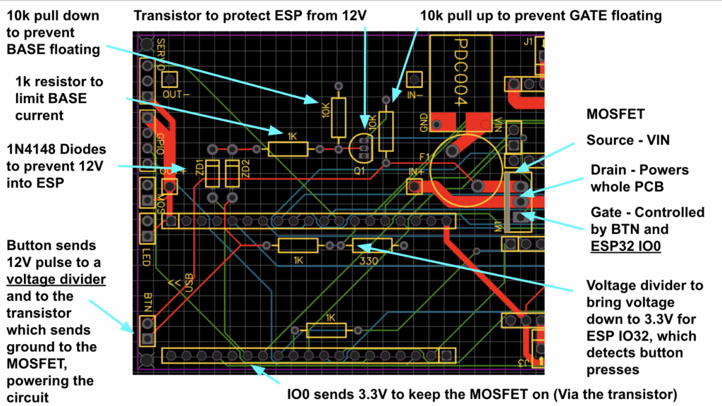
I kept experimenting, trying to piece together something that worked through trial and error. What I finally arrived at was a circuit where the pushbutton sends a 12 V pulse into a small transistor, which in turn pulls the gate of a P-MOSFET low to power the board. Once the ESP32 boots, it latches the transistor on with its own 3.3 V GPIO, so power stays stable even after the button is released. Pressing the button again produces another 12 V pulse, but this time it’s stepped down through a divider into one of the ESP32’s inputs. That tells the ESP32 to send the shutdown command over USB, wait until the Jetson is finished, and then release the latch. At that moment the transistor turns off, the P-MOSFET gate floats back up to 12 V, and the whole board powers down cleanly.
It wasn’t something I pulled from a schematic online, it was the result of a lot of trial, error, and learning what didn’t work before finally building the circuit that did.
With the motors, shutdown circuit, and wiring all tested, I finally reached the fun part: designing the PCB that would tie it all together.
Designing The PCB
The first step in creating a PCB is choosing the right design software. For me, that was EasyEDA. From the moment I tried it, the workflow felt natural and straightforward. I had experimented with KiCad, but I found the interface less intuitive and it lacked an easy way to share my work online. EasyEDA’s built-in online viewer made collaboration simple, allowing my coworkers to review designs without installing extra software. On top of that, it integrates seamlessly with JLCPCB, the manufacturer we selected, which streamlined the entire design-to-fabrication process.
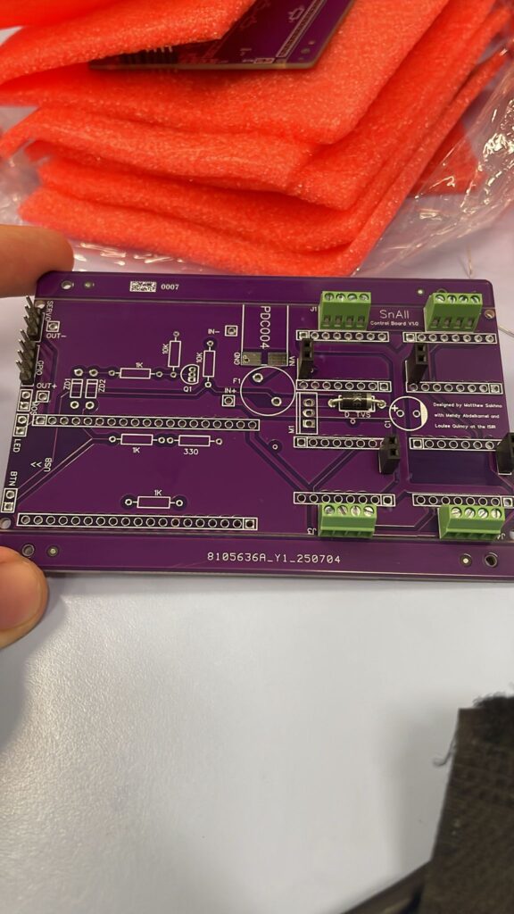
After many revisions I landed on this final design.
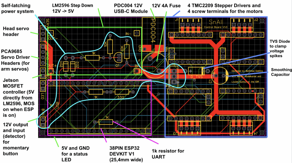
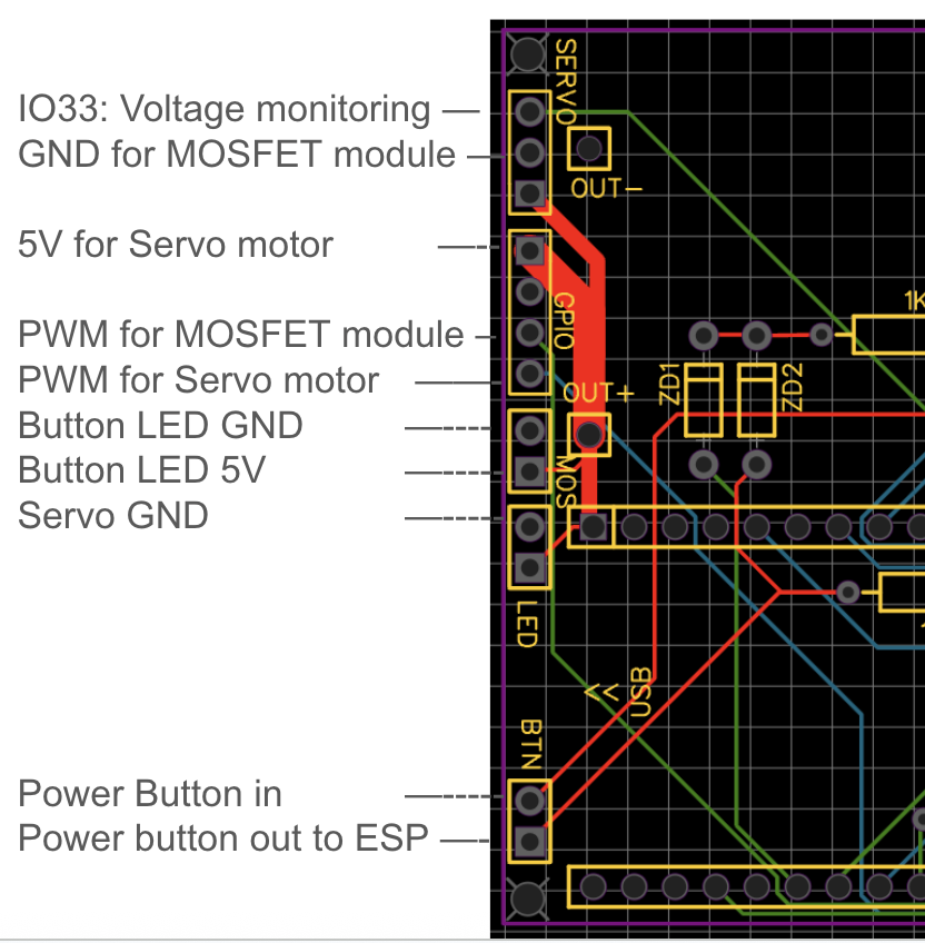
Power System
The circuit starts with 12 V input at the PDC004 module, which then passes through a 12 V / 4 A fuse before entering the source of a P-channel MOSFET. This MOSFET is switched by pulling its gate to ground. The gate itself is controlled by another P-channel MOSFET (originally a transistor, but more on that later).
The second MOSFET’s source is tied to ground, and its gate connects to two fast-switching diodes. One diode leads to a normally-open pushbutton that provides a 12 V pulse when pressed. The other connects to an ESP32 GPIO pin, which supplies 3.3 V to hold the MOSFET on once the button is released. This setup powers on the robot with a single press.
For shutdown, the system monitors the button press through another ESP32 GPIO pin. The pin is connected (through a voltage divider for safety) to the same trace as the N-MOSFET gate, so it can detect when the button is pressed without exceeding 3.3 V. When pressed again, the ESP32 sends a shutdown signal over USB to the Jetson, and then turns off the circuit, giving the Jetson time to shut down safely since it runs on a separate power supply.
Protection and Smoothing
Towards the stepper motor drivers there is a TVS diode to clamp voltage spikes and a smoothing capacitor. I added these because stepper drivers are noisy loads — when the motors decelerate or switch phases, they can kick energy back onto the supply rail. Without protection, those spikes could stress the MOSFET latch circuit or even the Jetson. The TVS diode safely clamps any overvoltage by dumping the excess energy to ground, and the capacitor absorbs the short bursts of current so the supply line stays smooth. Together they make sure the power rail feeding the robot is both stable and protected, even when the motors are switching hard.
Control and GPIO Pin Shortages
Control-wise, the ESP32 is connected to 4 stepper motor drivers, a voltage divider from the battery to read its voltage, a servo motor to control the robot’s head tilt, and a MOSFET module to turn on the Jetson. Each stepper motor driver is connected to 4 GPIO pins (STEP, DIR, DIAG, INDEX), needless to say, I ran out of GPIO pins fast. That’s why I had to use some boot pins, but I chose them carefully.
For example, GPIO0 is normally used to enter programming mode if held low during reset. I wired it into my self-latching power circuit, but the way I designed it ensures the pin stays high at reset, so the ESP32 still boots normally. GPIO2 is also a strapping pin with an internal pulldown. I left it unused because pulling it high at reset could cause boot problems. GPIO4 and GPIO5 are strap pins too, but I only used them as diagnostic inputs from the TMC2209 drivers (DIAG and IDX). Since the drivers don’t actively drive those pins during power-up and I don’t add strong external pulls, the ESP32’s internal strapping logic still wins at reset. GPIO15 is another boot-sensitive pin. I needed it for a step signal (M4 STEP), so I made sure the stepper driver doesn’t drive this pin during reset. That way, it stays floating/high and doesn’t block boot.
By mapping things this way, I managed to reclaim enough pins without interfering with the boot process, the ESP32 starts cleanly every time, and I still get all the functionality I need for motors, sensors, and power control.
UART Communication
On the communication side, all four TMC2209 drivers share a single UART with the ESP32. The ESP’s TX line fans out directly to all the drivers’ RX pins, while their TX pins are tied together and then pass through a 1 kΩ resistor before reaching the ESP32’s RX.
Each TMC2209 already has a built-in resistor on its TX output, which keeps the drivers from shorting directly against each other. The extra resistor at the ESP32 side is there to make the bus more robust: it limits any stray current into the microcontroller if two drivers talk at the same time, it damps down noise on the shared line, and it acts as a safeguard in case another chip without the built-in protection ever ends up on the same bus.
That’s why you’ll see it in all the reference designs, not because the system won’t work without it, but because it makes the communication line far more reliable and harder to kill.
With the PCB finalized, I sent it off for manufacturing. While waiting for it to arrive, I switched gears and focused on the software, starting with the robot’s object detection interface.
Object Recognition
The next challenge was giving the robot the ability to see and understand its surroundings. Object recognition was the foundation for everything that would follow: navigation, interaction, and even user-defined behaviors. My goal was to design a system that could detect everyday items out of the box, but also learn new, custom objects defined by the user.
The frontend is built with HTML/JavaScript, while the backend runs on a FastAPI server powered by multiple AI models. For general-purpose detection I used YOLOv5 (via ONNX Runtime for speed), and for custom object recognition I implemented NanoOWL alongside MobileNetV2 embeddings, using an Intel OAK-D depth camera to provide both RGB and depth data. Custom object embeddings are stored directly on the Jetson’s local file system.
The system has two modes. In Save Objects Mode, users can enter custom names (like “Red Mug” or “My Keys”), upload multiple photos from different angles, and save those objects into the recognition system. They can also view and manage all their saved items. In Detect Objects Mode, users choose which objects they want to detect from a checklist, then see them highlighted in the live camera feed with bounding boxes, confidence scores, and distance measurements.
I can’t share the full codebase, but here are some representative snippets showing how the system works.
Object Recognition Engine
YOLOv5 for predefined objects (80+ COCO classes):
# Load YOLOv5n ONNX model and COCO classes
YOLOV5N_ONNX_PATH = 'yolov5n.onnx'
COCO_NAMES_PATH = 'coco.names'

with open(COCO_NAMES_PATH, 'r') as f:
    COCO_CLASSES = [line.strip() for line in f.readlines() if line.strip()]

ort_session = ort.InferenceSession(YOLOV5N_ONNX_PATH)
MobileNetV2 embeddings for user-defined objects:
# MobileNetV2 for embeddings
mobilenet = mobilenet_v2(pretrained=True)
mobilenet_embed = torch.nn.Sequential(
    mobilenet.features,
    torch.nn.AdaptiveAvgPool2d((1, 1)),
    torch.nn.Flatten()
)
When saving objects, the system:
- Extracts embeddings from uploaded images
- Stores them in a pickle file (
custom_object_embeds.pkl) - Uses cosine similarity during detection
Detection combines two complementary methods:
- Checking YOLOv5 boxes for potential matches
- Scanning the whole frame with a sliding window
# Custom object detection using YOLO boxes
custom_dets_yolo = detect_custom_objects_yolo_boxes(
    frame_bgr, yolo_boxes_for_custom,
    object_names=requested_objects, threshold=0.6
)

# Sliding window custom detection
custom_dets_sw = detect_custom_objects(
    frame_bgr, object_names=requested_objects, threshold=0.6
)
Key Technical Challenges
1. Running multiple AI models efficiently
- Solution: Moved YOLOv5 to ONNX Runtime for faster inference, added a configurable sliding-window stride, and scheduled YOLO runs first with custom detection filling in the gaps.
2. Bounding box misalignment between models
- Solution: Wrote a scaling/transform function to map YOLO’s resized inputs back to the original frame cleanly.
def preprocess_yolo_image(frame_bgr, img_size=640):
    # Resize and pad image for YOLOv5
    r = img_size / max(h0, w0)
    new_unpad = (int(round(w0 * r)), int(round(h0 * r)))
    # ... padding logic ...
    return img, r, (dw, dh), (w0, h0)
3. Adding real-world distance measurements
- Solution: Combined YOLO detections with OAK-D depth frames. For each bounding box, the system computes the average depth inside the region.
def get_average_depth_in_box(box, frame_shape):
    x0, y0, x1, y1 = box
    # Extract depth data from bounding box region
    return average_distance
Wrapping Up
By combining YOLOv5’s broad object detection with custom embeddings and depth data, I built a recognition system that can spot everyday items while also learning user-defined ones. With object detection complete, the next step was developing the visual block editor, which would let users build behaviors for the robot without writing a single line of code.
Blockly Editor
Once the robot had vision and recognition capabilities, the next step was to give users a way to program behaviors without writing code. To achieve this, I built a robot control interface that combines visual programming with real-time computer vision and robotics. The environment includes both a Blockly-based visual editor and a Python text editor, all connected to a FastAPI backend that communicates with the physical robot.
To make the visual editor useful for robotics, I designed a set of custom blocks that map directly to robot actions and sensing functions:
Blockly.defineBlocksWithJsonArray([

{

"type": "when_flag_clicked",

"message0": "when flag clicked",

"message1": "%1",

"args1": [{ "type": "input_statement", "name": "DO" }],

"colour": 65

},

{

"type": "object_detected",

"message0": "object %1 detected?",

"args0": [{ "type": "field_input", "name": "OBJECT", "text": "object_name" }],

"output": "Boolean",

"colour": 230

}
// ... more blocks

]);
The blocks are organized into intuitive categories:
- Events: script triggers (e.g. “when flag clicked”)
- Motion: robot movement commands
- Line Following: specialized blocks for tracking lines
- Control: loops, conditionals, and flow control
- Sensing: object detection and distance measurement
- Operators: logic and math operations
Live Camera Feed
The interface integrates the live vision system so programs can react to the environment. Whenever object detection blocks are used, the camera feed is automatically activated:
function checkCameraUsage() {

const code = Blockly.JavaScript.workspaceToCode(blocklyWorkspace);

const usesCamera = code.includes('isObjectDetected') ||

code.includes('getObjectDistance');

if (usesCamera) {

cameraContainer.style.display = 'flex';

startCameraFeed();

startDetectionTracking(code);

}

}
Detections appear as bounding boxes overlaid on the video stream:
function drawDetectionBoxes() {

currentDetections.forEach(detection => {

if (detection.box && detectedObjects.has(detection.class)) {

const [x1, y1, x2, y2] = detection.box;

const box = document.createElement('div');

box.className = 'detection-box';

box.style.left = (x1 / 640 * 100) + '%';

box.style.top = (y1 / 360 * 100) + '%';

// ... positioning logic

}

});

}
Command Tracking & Backend Communication
To make debugging easier, every command is logged in a real-time display with timestamps:
function addCommandDisplay(action, result, type = 'result') {

const time = new Date().toLocaleTimeString();

const commandDiv = document.createElement('div');

commandDiv.innerHTML = `

<span class="time">${time}</span>

<span class="action">${action}</span>

<span class="${resultClass}">${result}</span>

`;

}
The frontend communicates with the robot through FastAPI endpoints, which handle movement commands, camera streaming, and object recognition:
@app.post("/move")

def move_robot(cmd: Command):

return move_robot_command(cmd.action)

@app.get("/api/camera/feed")

def get_camera_feed():

return StreamingResponse(mjpeg_stream(),

media_type="multipart/x-mixed-replace; boundary=frame")

@app.post("/api/object-recognition/detect")

async def detect_objects(request: Request):
Robot movement commands are passed over serial to an Arduino controller:
def move_robot_command(action: str):

if ser and ser.is_open:

command_to_send_to_arduino = f"{action}\n"

ser.write(command_to_send_to_arduino.encode('utf-8'))

return {"status": "ok", "received": action}
Script Management
Finally, the system allows saving and reloading Blockly scripts, making it easy to reuse and share robot programs:
function saveScript() {

if (currentMode === 'blockly') {

const xml = Blockly.Xml.workspaceToDom(blocklyWorkspace);

const xmlText = Blockly.Xml.domToPrettyText(xml);

downloadFile('blockly_script.xml', xmlText, 'application/xml');

}

}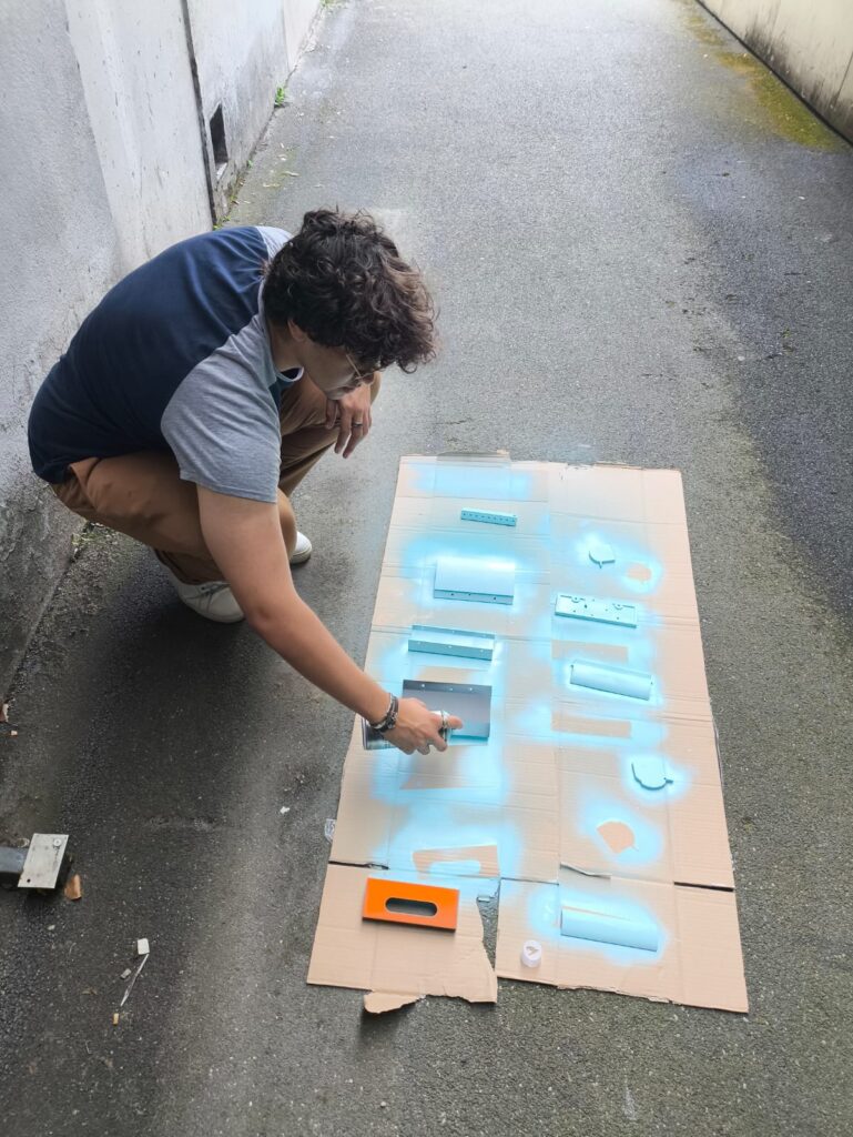
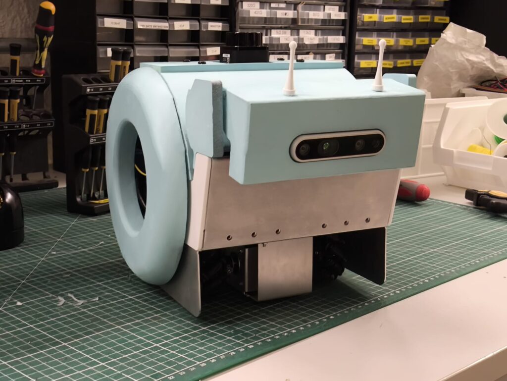
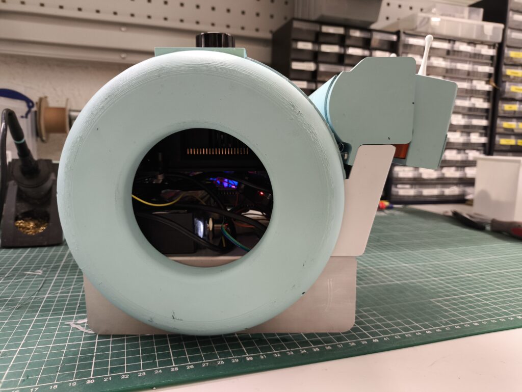
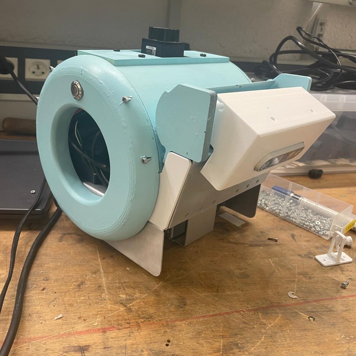
Then we painted the shell and put everything inside!
Wrapping Up
By combining visual programming with computer vision, the Blockly editor turns complex robotics tasks into drag-and-drop building blocks. Users can create programs that respond to real-world events—like moving toward a detected object or following a line, without writing a single line of code. With the block editor complete, the next step was preparing the Jetson Orin Nano, which would serve as the brain of the robot and run the full AI stack.
Jetson Orin Nano Setup
The Jetson Orin Nano was the natural choice for the robot’s brain, it’s powerful enough to handle computer vision, SLAM, and reinforcement learning, yet compact enough to fit inside the platform. But before I could start running heavy AI workloads, I needed to set it up with fast, reliable storage.
Because the Jetson needed to handle SLAM and reinforcement learning, reliable storage was essential. I decided to install an NVMe SSD, but my first attempt didn’t go smoothly. I initially tried a PNY CS1030, flashing it in an external NVMe enclosure and attempting to boot from it on the Jetson. No matter the method, I kept running into the same error in NVIDIA SDK Manager: the drive simply wouldn’t initialize properly.
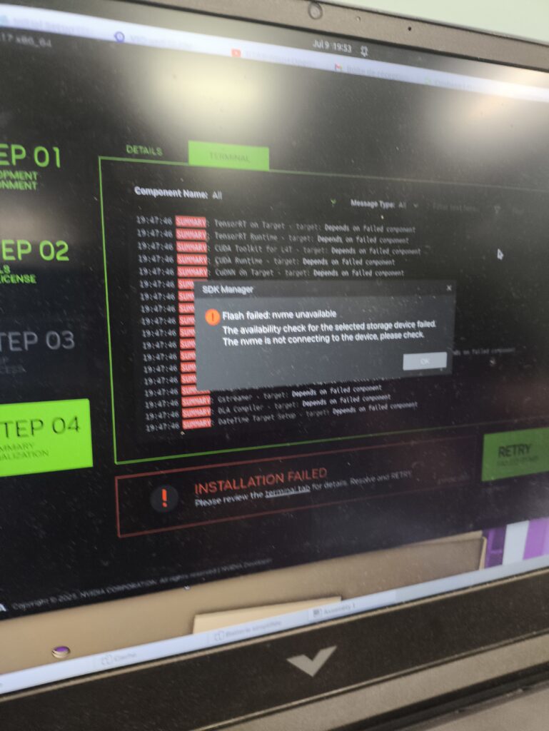
Here’s a picture of the error that I kept on getting in the NVIDIA SDK Manager.
The culprit was the CS1030’s lack of a DRAM cache. Without onboard memory to store its mapping table—and no Host Memory Buffer (HMB) support to use system RAM—it became unstable during boot. The Jetson’s bootloader couldn’t handle the slow initialization, causing the process to fail.
I replaced it with a Lexar NM620, which includes HMB support, and it worked perfectly right away. With that upgrade, the Jetson recognized the drive instantly, and I had a fast, stable base for running heavier AI workloads.
SLAM
With the Jetson finally running on stable storage, the next step was giving the robot the ability to map its environment and localize itself. For that, I needed a SLAM (Simultaneous Localization and Mapping) system that could generate accurate 3D maps while also integrating with the sensors we planned to use in teaching,namely LiDAR and wheel odometry.
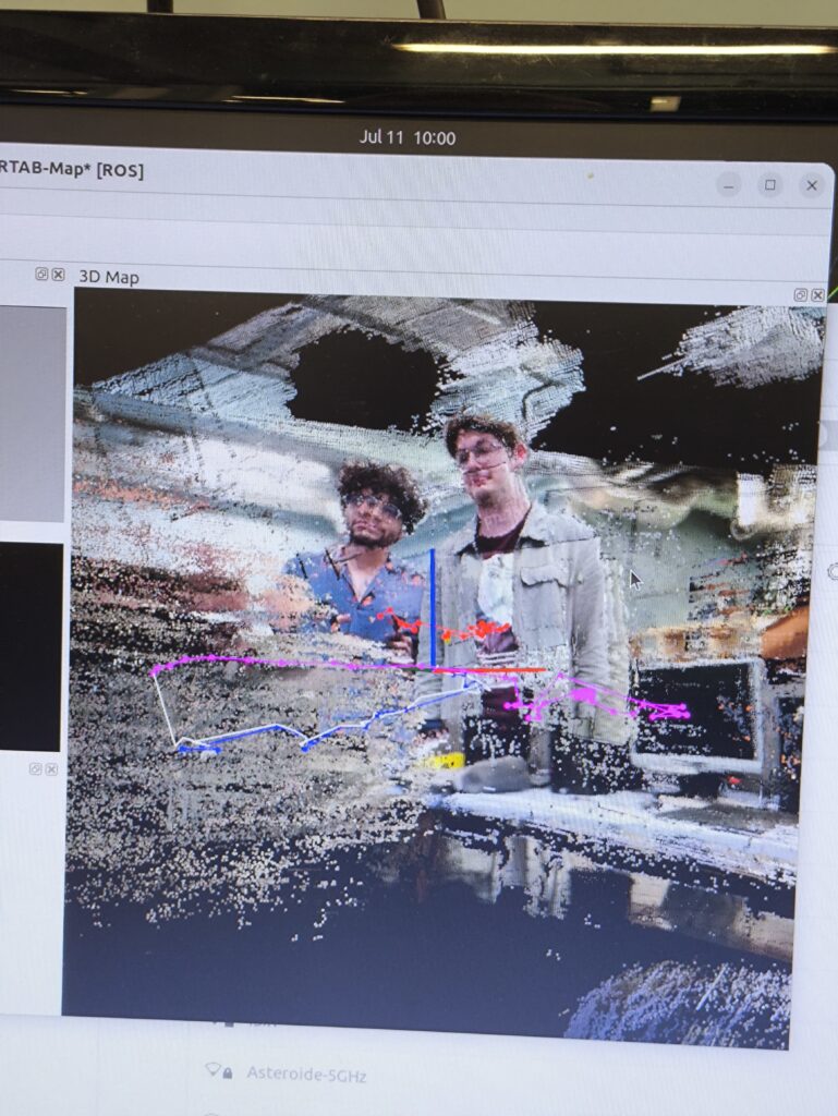
For mapping and localization, I chose RTAB-MAP SLAM. Its ability to generate voxelized 3D maps, combined with support for both LiDAR and wheel odometry, made it ideal for robotics teaching. NVIDIA’s own Isaac ROS Visual SLAM was tempting since it’s highly optimized for the Jetson, but it lacked LiDAR integration and wheel odometry input—both features that were essential for our use case.
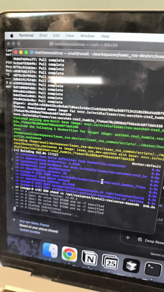
Getting RTAB-MAP running on the Jetson wasn’t straightforward. My first attempt, building it from source, was painful: compilation took hours, and many dependencies failed on ARM. Eventually, I switched to using Docker, which worked flawlessly and saved a lot of time. Once it was running, I piped the data into three.js to create a browser-based visualization of the 3D point cloud.
How It Works
- HTTP Request: The function sends a POST request to /rtabmap/start endpoint
- Backend Processing: The FastAPI backend receives this request and starts the rtabmap process
- Status Check: After starting, it immediately calls updateRtabmapStatus() to verify the service is running
- Error Handling: If the service fails to start, it logs the error
- Users don’t need to run any commands
- Automatic startup: SLAM starts as soon as the page loads
- Real-time monitoring: Status is checked every 5 seconds
- Graceful shutdown: Service stops when the page is closed
- Error recovery: Failed starts are logged and can be retried manually
This creates a seamless experience where opening the SLAM page immediately begins the mapping process without any technical setup required from the user.
Wrapping Up SLAM
By running RTAB-MAP inside Docker and visualizing its maps directly in the browser with three.js, I built a SLAM system that was both powerful and user-friendly. With mapping in place, the next step was to assemble the hardware and test the robot with my custom PCB.
Assembly
PCB Soldering
My PCBs had finally arrived from manufacturing, and I was eager to see the full system come to life.
Assembly went smoothly at first, soldering components, wiring connections, and running initial power tests. Everything worked perfectly on the first try… except for one critical feature: the soft shutdown system. It would behave very strangely, sometimes it wouldn’t turn on, and other times it wouldn’t turn off.
What I thought would be a quick fix turned into three long days of debugging. In the end, the solution was surprisingly simple: replacing the BJT transistor with an N-channel MOSFET.
At first glance, a bipolar junction transistor (BJT) seems like a good candidate for switching. But in a circuit that depends on precise voltage thresholds, its quirks become deal-breakers:
- Finite VCE: Even in saturation, the BJT drops a few hundred millivolts. That was just enough to throw off the delicate thresholds in my soft shutdown loop.
- Leakage currents: A BJT never turns fully “off.” Tiny leakage currents can sneak through and keep the latch partially powered, preventing a clean shutdown.
- Storage charge: When saturated, a BJT stores charge in its base. This makes turn-off sluggish and unpredictable, again disrupting the shutdown sequence.
Put together, these factors meant the BJT couldn’t deliver the switching my design required.
To make things worse, the transistor pads on my PCB were really close together, so it was way too easy to accidentally bridge connections while soldering—which definitely didn’t help during debugging.
Once I replaced the BJT with an N MOSFET, everything worked exactly the way it was supposed to. The soft shutdown finally behaved reliably, and with the hardware fully assembled and tested, I could move forward knowing the robot had a solid foundation for the full assembly.
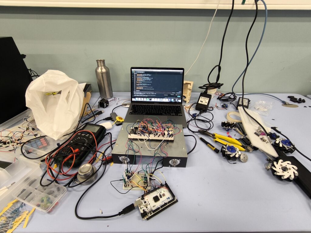
Full Electrical Assembly
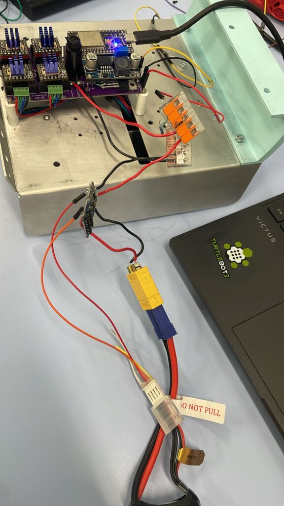
Here’s the first prototype of the electrical assembly. It’s without the battery or BMS. The PCB and Jetson are powered by their respective power supplies.
What you may notice is the slow speed that it has. This is beacause the stepper motors that we chose were underpowered. This was a pretty easy fix though because I quickly found some motors with more torque and swapped them.
Next I installed the battery. The positive and negative of a 5000mAh battery, along with the balance wires, are connected to a 3S BMS which then goes out to a wago connector. This wago connector connectes to the PCB power, the Jetson DC Jack (not pictured here), the 3S CC-CV charger (not pictured here), and the voltage divider for the ESP32 to measure the battery level. This was pretty messy though. The reason it’s this messy is because intially the whole power system was supposed to be powered by a power bank. My supervisor insisted on this solution but eventually we conviced him to change his mind. The result of this late change is a battery system that is messier than what I would’ve wanted. It’s something to do for the next version of Sn.AI.l!
The Final Result
After weeks of design, debugging, and assembly, Sn.AI.l finally came to life. Inside its painted shell sits a fully custom electrical system: my PCB powering four stepper motors, a safe shutdown circuit protecting the Jetson Orin Nano, and a clean interface tying everything together. On the software side, Sn.AI.l can see and recognize objects, map and navigate its environment, and even learn behaviors through reinforcement learning. From simple Blockly scripts to advanced Python code, it gives students multiple entry points into robotics and AI, all wrapped in a system that’s approachable yet powerful. Seeing the robot drive around, detect objects, and run programs I built from scratch was one of the most rewarding moments of my internship.
Conclusion
What started as an unexpected opportunity quickly became one of the most challenging and rewarding projects I’ve ever worked on. In just a few months, I went from breadboard prototypes and messy wires to a fully functioning educational robot powered by AI. Along the way, I learned to design PCBs, troubleshoot complex circuits, optimize AI models, and build full-stack interfaces that connect hardware, software, and users.
Sn.AI.l is more than just a robot, it’s a teaching tool meant to make AI tangible, interactive, and exciting for the next generation. For me, it was also proof that with persistence, curiosity, and a bit of trial and error, even a first-year student can lead to great results solving real world problems. This project has fueled my passion for robotics, electronics and AI, and I’m leaving ISIR not only with technical skills but with the confidence that this is the field I want to dedicate myself to.